Consolidation of underground rockfill for increased ore recovery: the Toguraci case study
PT Nusa Halmahera Minerals (PT NHM) is an Indonesian joint venture company owned by Newcrest Mining Limited (75%) and PT Aneka Tambang (Persero) (25%). PT NHM operates two underground gold mines, Kencana and Toguraci at the Gosowong mine site in North Halmahera District, North Maluku Province, Indonesia.
Due to several major stope over-break events at Toguraci, NHM changed the mining method from a bottom-up Avoca stoping approach using waste rock as fill material and leaving sill pillars; to a top-down open-stoping method using paste fill without sill pillars.

The revised mine plan originally had stoping progressing from the current operating level to the base of reserves followed by extraction of the sill pillars at the interface between the two mining methods at the end of mine life. Geotechnical modelling was conducted on the revised mine plan. It was recommended that these high-grade sill pillars be extracted earlier in the mine sequence. This reduced the risk of pillars overstressing, and more difficult recovery at the end of mine life. The backfill material above the sill pillars is unconsolidated run-of-mine development waste rock or unconsolidated rockfill (URF).
Due to earlier attempts to extract sill pillars under URF not being successful in the upper areas of the mine, it was stipulated that the URF above the five remaining pillars must be consolidated prior to stoping. Cost-benefit analysis showed this to be justifiable due to the high grade of the ore locked up in the pillars.
Key to design of the consolidated rockfill (CRF) was having a suitable product in place with sufficient strength and quantity to tolerate stresses and to prevent caving of the URF as this would sterilize or dilute the ore, and potentially cause regional instability due to large amounts of fill mobilizing.
Approach
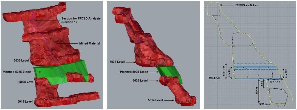
As an example, in TY5025 of Yahut Iode (Figure 1), the geometry of the hangingwall (HW) and the wide span, up to 15 m, required a degree of conservatism. Here a factor of safety (FOS) of 2 was considered acceptable and the extraction sequence was assessed. The TY5025 pillar was extracted as two parallel stopes on the hanging wall and footwall with the one being backfilled with paste before mining the other. With an assumed failure span of 7.2 m, and with the HW extracted first, the FOS of 2 was achieved with 4 m to 5 m of grout, whereas extraction of the footwall and the same conditions required 5 m of grout for a FOS of 2.
In Yahut TY5015 the narrower orebody resulted in a higher FOS for 5 m thickness and indicated a CRF height over 4 m was acceptable for spans between 6.7 m and 7.4 m. Above the Damar Iode pillars five-metre-thick consolidation was required.
Grout was initially planned on site to be injected in one pass through pre-installed self-drilling anchors (SDA) in a 2.5 m pattern. Initial attempts to do this failed due to the small SDA aperture, the annulus outside the SDA, grout consistency and insufficient means of quality assurance or quality control.
Consequently, the use of SDAs was discarded and an alternative method of injection was developed utilizing open holes. The revised grouting method used the same grout product and grout pump but modified the way the grout was delivered to the URF. The revised method focused on addressing several factors identified from early work:
- Larger diameter drillholes created a larger surface area in the hole exposing more voids to receive grout. The 89 mm retractable drill bit provided a suitable hole size for successful grouting, and could drill URF without getting stuck. Drill holes 76 mm in diameter were also used, the maximum diameter on the Cablebolter, but were problematic due to the coupling sitting behind the drill bit causing rods to get jammed.
- The 40 mm PN16 pipe from the pump was inserted directly into the holes providing a uniform and larger aperture for grout delivery.
- Holes to be grouted were drilled several rings apart to reduce leaks or backfilling of holes.
- Quality control processes were established including probe drilling and camera inspections. These were key to the success of the project.
Grout mixture
A design grout mixture of 2:1 water:grout was required. To check the mixture ratio, samples were collected during pumping in one litre cubed polystyrene moulds (cube samples) and weighed while wet. The specification required cube sample weight of 1250 g for 2:1 water:grout. A weight of 1260g was targeted to ensure a suitable strength was achieved.
When a cube sample weight varied from the required 1260 g during injection the rate of water feed at the pump was adjusted up or down to compensate, and a new sample was taken.
Strength testing
Cube samples were cured for three, seven or 14 days and were tested for unconfined compressive strength (UCS) strength on site. Results show the UCS for 2:1 water:grout averaged approximately 8 MPa with a range between 4 MPa and 16 MPa.
Camera inspections
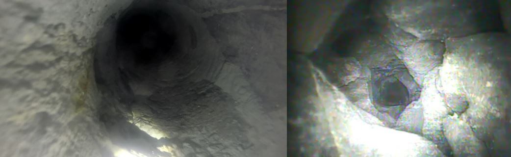
A camera was used to inspect holes, initially frequently and periodically thereafter. A specifically designed up-hole camera was acquired with a stiff cable and reel feeder and protected camera lens. The camera was fed up the holes from the integrated tool carrier basket. The cameras confirmed the condition of the URF and the grout, and the presence of pre-existing paste in some cases. An example of injected grout is shown in Figure 2a. The nature of some voids is shown in Figure 2b.
Probe drilling
The length to breakthrough from CRF into the UCF was measured in each drillhole. The vertical thickness of the grouted layer was calculated from this and plotted for each drive (Figure 7). Drill sites were chosen to check recent injection using the 2.5 m spaced ring design in case further grout was required. The grout was shown to flow along the URF and build up where it was injected. Drilling was delayed 24 hours after grouting to allow the grout to cure. Once the grout had cured the levels in holes was confirmed through probing campaigns.
In practice
Rate of Injection
The rate of injecting in each level was initially slow. This was due to leaks, filling of cracks and fissures, and holes drilled only two metres past breakthrough restricting void volumes to fill. Initial injection sealed the bottom of the UCF and flow direction became more predictable. Second pass drillholes were drilled to the top of the target zone providing greater volumes to grout with less hole changes, hence more tonnes per shift.
Once areas were close to filled, injection locations became more selective, smaller volumes were accepted before holes pressured up and hole changes were required more frequent.
Dilution when mining
The extraction method for mining of the pillars beneath the consolidation required blast holes to be drilled from beneath. Stopes were generally 15 m long with the sill pillars to be extracted 5 m to 10 m high. A maximum of two to three rings were fired at a time, depending on geotechnical conditions.
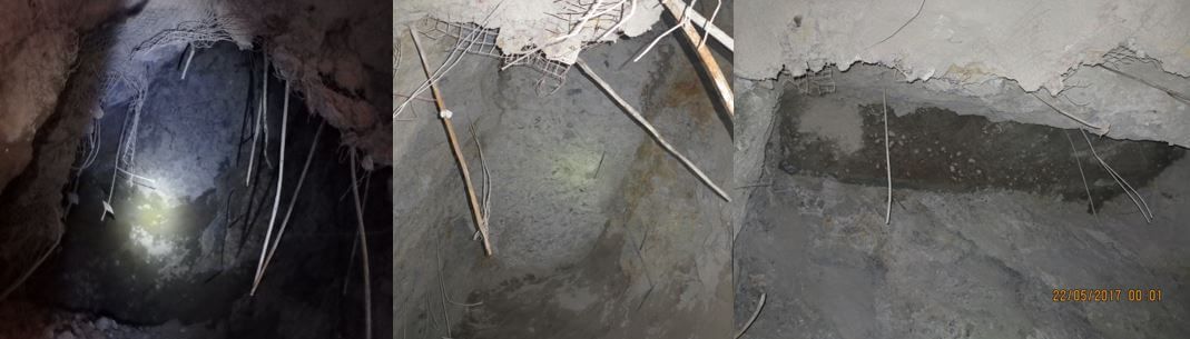
The consolidated URF exposed in the backs of the stopes in TY5025, TD4998 and TY5015 after mining has shown to hold up well. The consolidated backs look very similar despite the different URF encountered during injection. Figures 3a, 3b and 3c show the respective conditions seen, and suggest the nature of the material once grouted was similar.
Lessons learnt
Planning
Ensure the proposed design is aligned with site conditions and meets the required outcomes. With appropriate planning a trial of the proposed process will help guide set up. Be prepared to change the overall strategy and daily plans. Conduct a placement trial before locking in your implementation plan.
Drilling
Ensure the hole diameter is suitable for the pipe used and easy flow. Ring spacing should be comparable with the flow nature of the grout. Here 2.5 m spacing was reasonable. Drilling the first pass a limit of 2 m into the URF helped establish a sealing layer and consolidated the URF-pillar interface. Probe drilling close to recent grouting was best achieved at least 24 hours after injection.
Grout
Equipment should have sufficient aperture and the grout should be free of lumps. Grout mix was maintained at 2:1 water:grout ratio. A thinner mix would have reduced strength properties. The mix was thickened when excessive leaking occurred in an effort to seal the leaks. Cloth pads were used to block drillhole collars and larger leaks such as from split sets. If pads and/or thickening up the mix did not work the hole was stopped and returned to at a later date.
Leaks
- Predrilling of multiple holes in areas to be grouted created pathways for leakage and was stopped.
- Leaks from fractures in the rock were retarded by pretreating the backs with a layer of shotcrete.
- URF rill had been left exposed in level development at the base of the fill. These required shotcreting before grouting commenced to prevent leaks. Periodic checks were also required to confirm integrity of the shotcrete. Grout, or displaced water was observed leaking from the shotcrete on occasion.
- The presence of inaccessible headings with exposed URF should be clearly understood during the planning stage. These are developments such as sumps or cuddies that have been isolated by the URF but not backfilled leaving voids adjacent to the grouting target.
Support
- The pumps require consistent high volumes of water and air, and at sufficient pressure to push the grout up to 300 m without having it set in the pipe. Double-shifting activities benefited from a general hand familiar with the site available to support the grouting team. This role was to troubleshoot and facilitate effective changes quickly arising from changes in mining activities or breakdown of support equipment and services.
- Full time availability of IT support was required.
- Full time availability of a drill rig was critical, particularly on double shift. On single shift, drilling was achieved on night shift.
Stope Extraction
Stopes were not blasted for their full strike length in one firing. Blasting of only several rings at a time allowed monitoring of the performance in the consolidation, with the option to fill the incomplete stop before continuing. For pillars fired against intact rock vertical slot was used. For the pillars fired against paste backfill, a radial or drag slot was employed. On completion of the stope, a fill fence was constructed beneath the next pillar and the stope was filled with 1 MPa to 2 MPa paste backfill.
Acknowledgements
We would like to thank the management of PT. Nusa Halmahera Minerals and Newcrest Mining Limited for permission to write and publish this paper. Many thanks to the individuals both internally and externally who have shared their knowledge and put considerable effort into establishing a functioning grouting process, working with the changing conditions and making this project a success.
This article is based on the paper
Rockfill consolidation for the extraction of sill pillar stopes at Toguraci gold mine by A Proudman, J Isles, R Lawolo and G Forster presented at the 13th AusIMM Underground Operators’ Conference.

Andrew Proudman
Principal Consultant
Subscribe for the latest news & events